The GameShell
Table of Contents
Videos
Media ID: B5-nCCpopSw
Media ID: B6NUBEXocQB
Intro
What is the GameShell?
Take an ARM based SoC, create a custom, modular open source design to attach
- a battery
- a keyboard
- a display
called the ClockworkPi: https://www.clockworkpi.com/
Then, provide
- a custom launcher
- lots of emulators
- a case
to hold everything together and you have a gameboy you can show to your friends while SSH’ing into it ;).
If you are not familiar with SSH, there is a small menu that shows you the path you need to enter into your Windows File Explorer Address Bar, to access the folders to store the emulator roms or music files (yes it has a music player ;)).
My goal is to use this as a remote serial debugger for IoT experiments, as the GPIO port has two serial interfaces (see the Debug sheet here: https://github.com/clockworkpi/GameShellDocs/blob/master/clockwork_Keypad_Schematic.pdf).
The GitHub project is here: https://github.com/clockworkpi/.
The community page is here: https://forum.clockworkpi.com/.
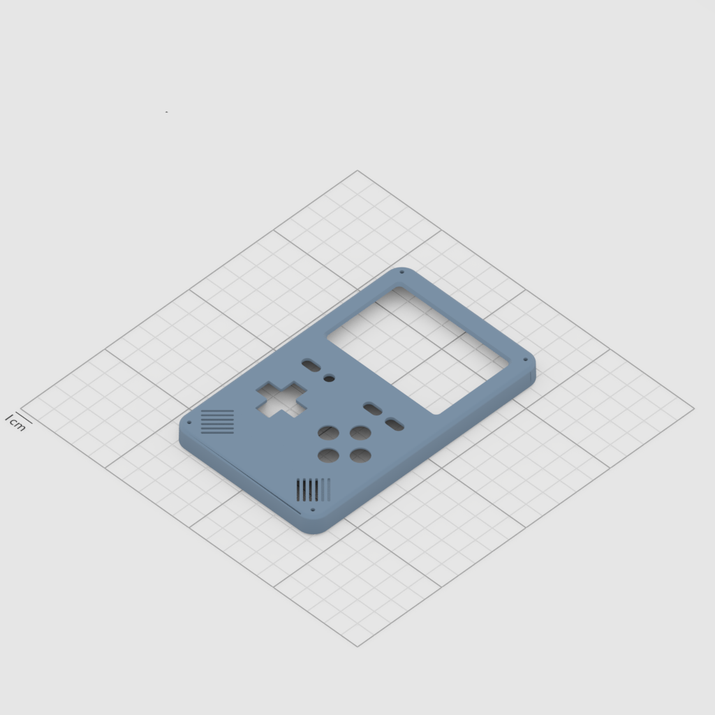
The Case Re-Design
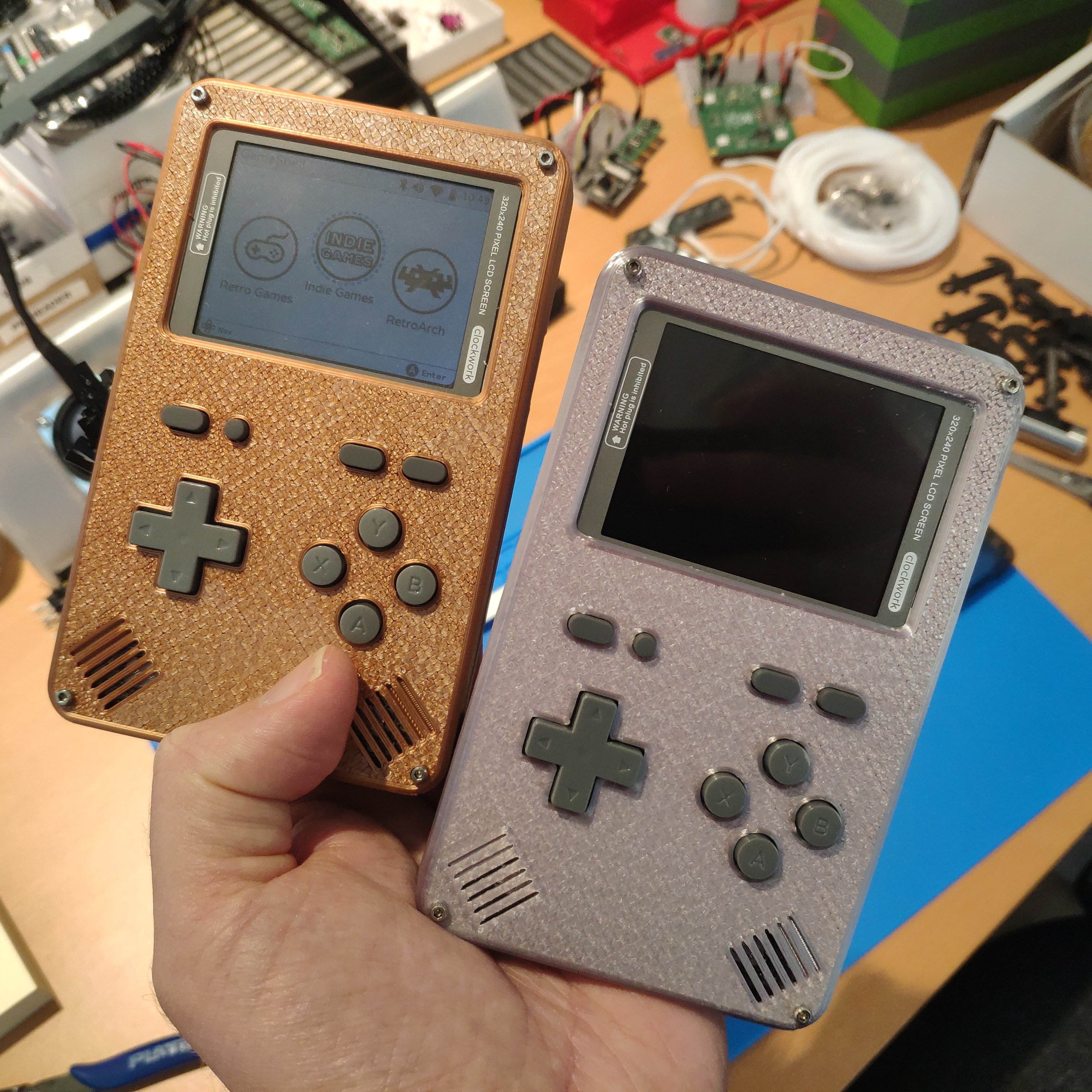
The original GameShell comes shipped with a front case and two back cases. The front cases are available in three colors: white, red and yellow.
If you want your GameShell to be in a different color, you can fetch the original .stl files from thingiverse: https://www.thingiverse.com/thing:2661013/files
These .stl files are the original design and are attached with a clip fit and two plastic wheels to the sides of the screen.
Printing the angles to attach the closing wheels to is still a bit flimsy with FDM printers, and requires support, so I removed these and went with four 16mm M2 hex screws to attach the cases.
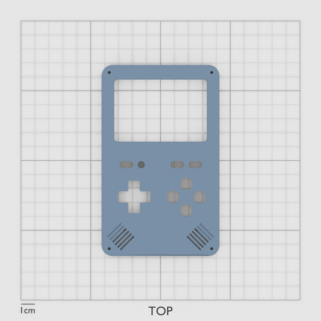
In addition to this I redesigned the speaker grill to resemble the original gameboy (but in stereo).
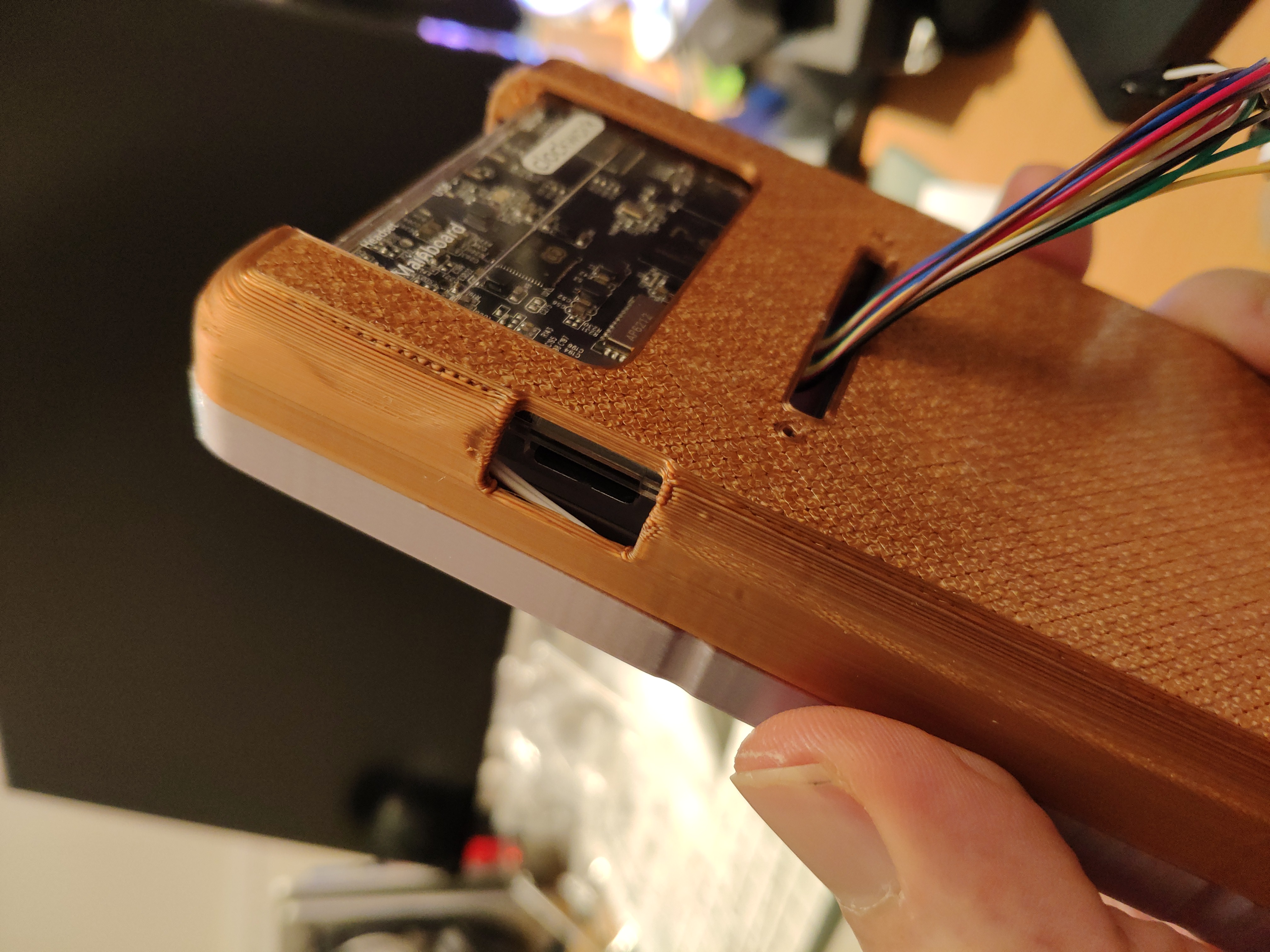
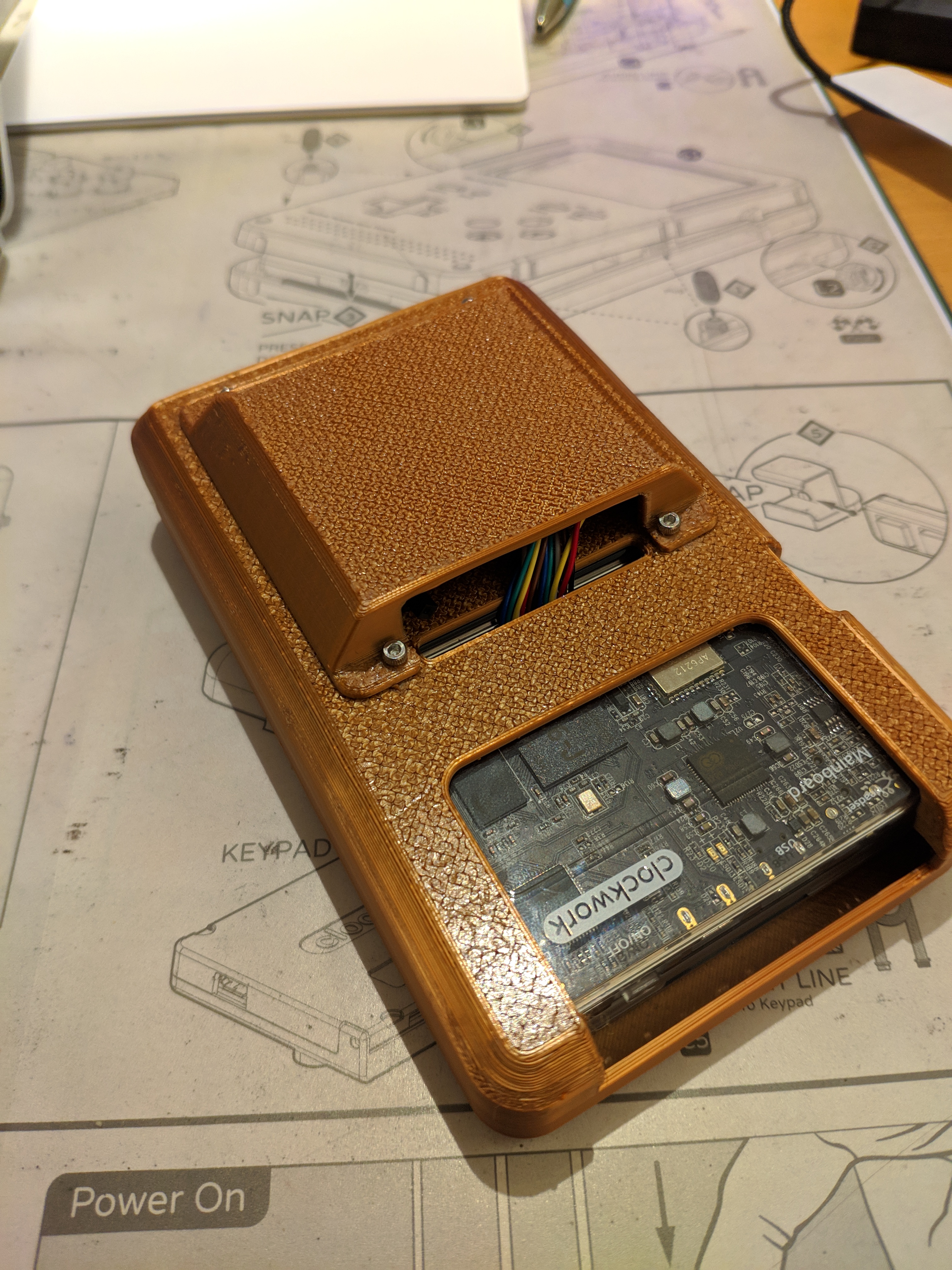
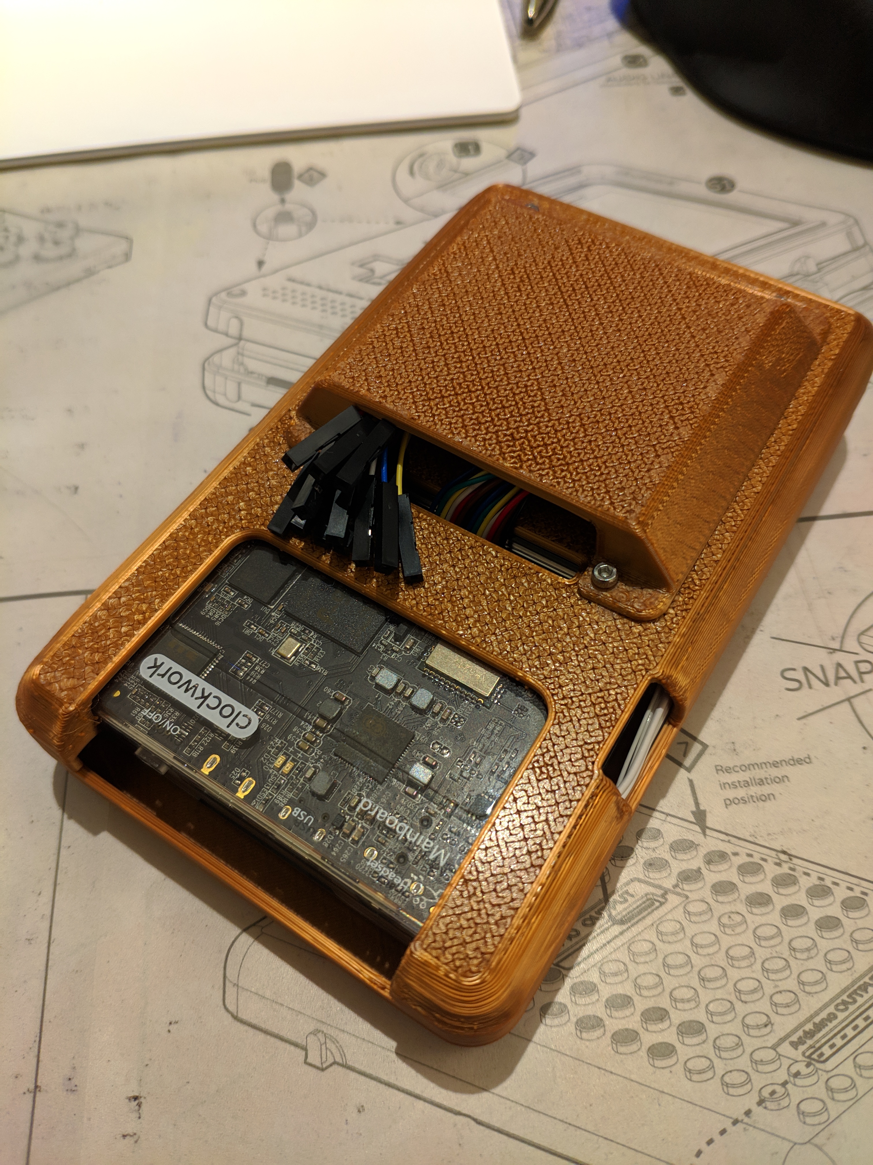
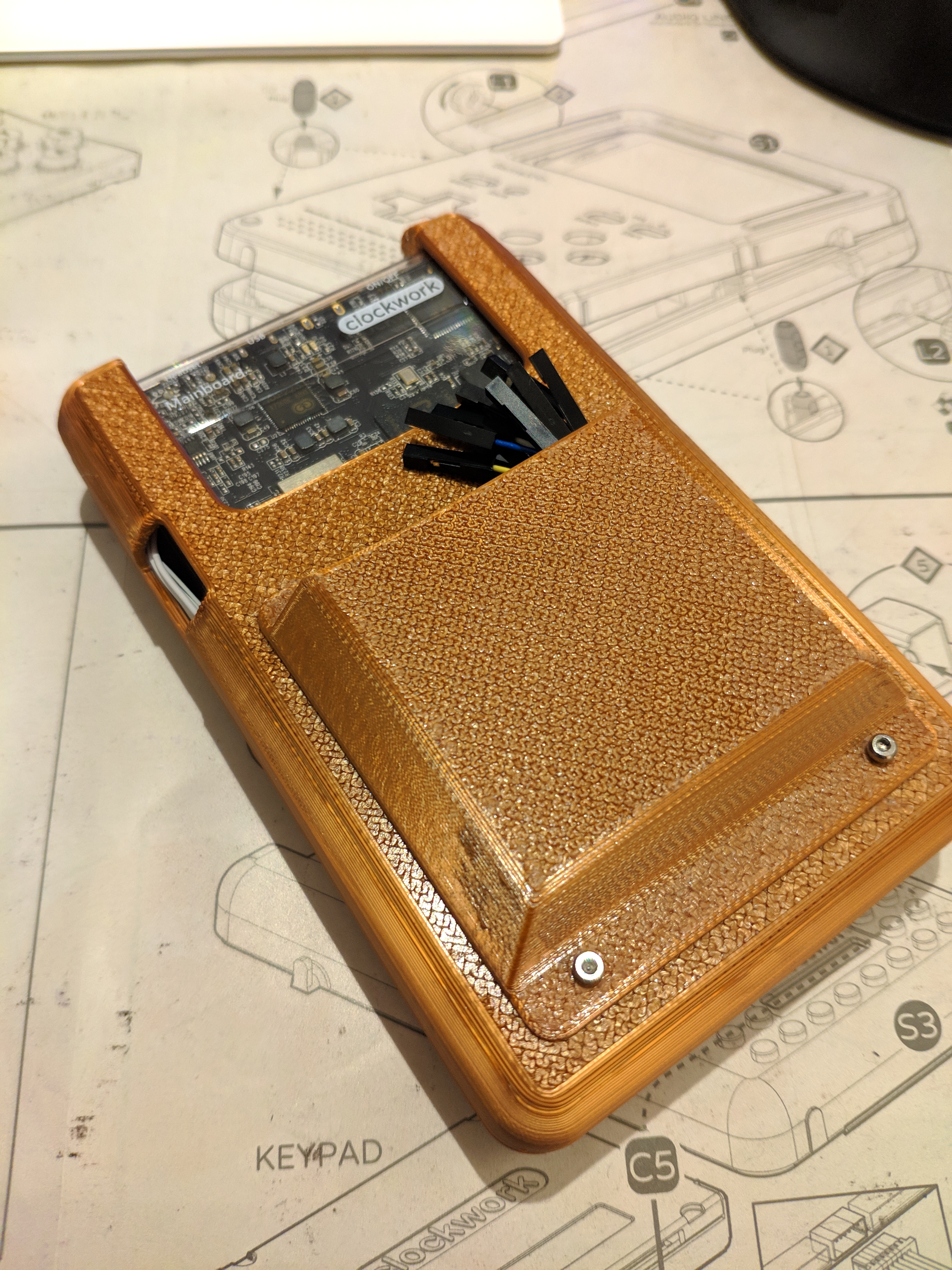
I added a slot to use the GPIO cables.
And the best part: A slot to access the micro sd card: :)
Download
You can download my redesigned files here: https://www.thingiverse.com/thing:4057477
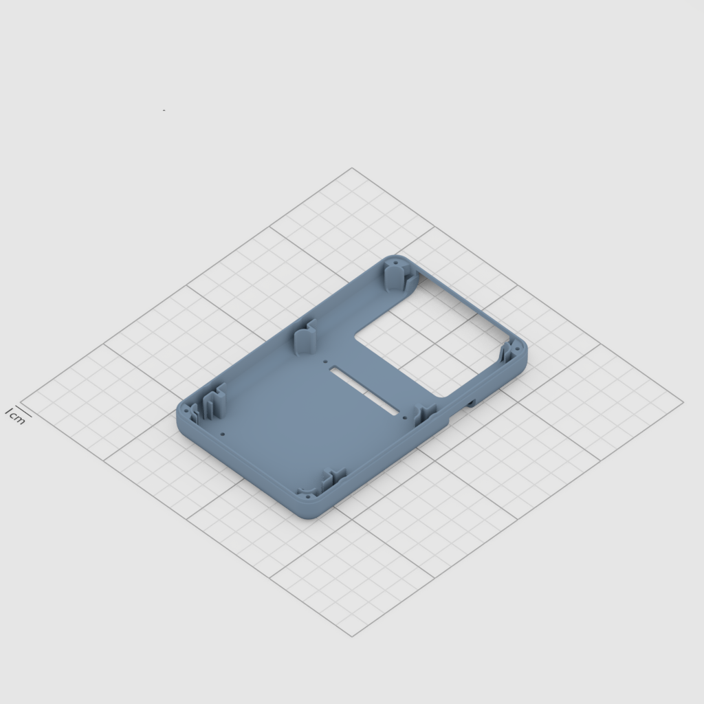
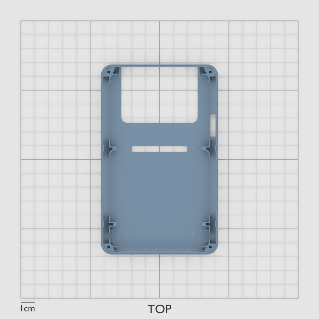
You can see the window to access the SD card slot, as well as the GPIO access slot.
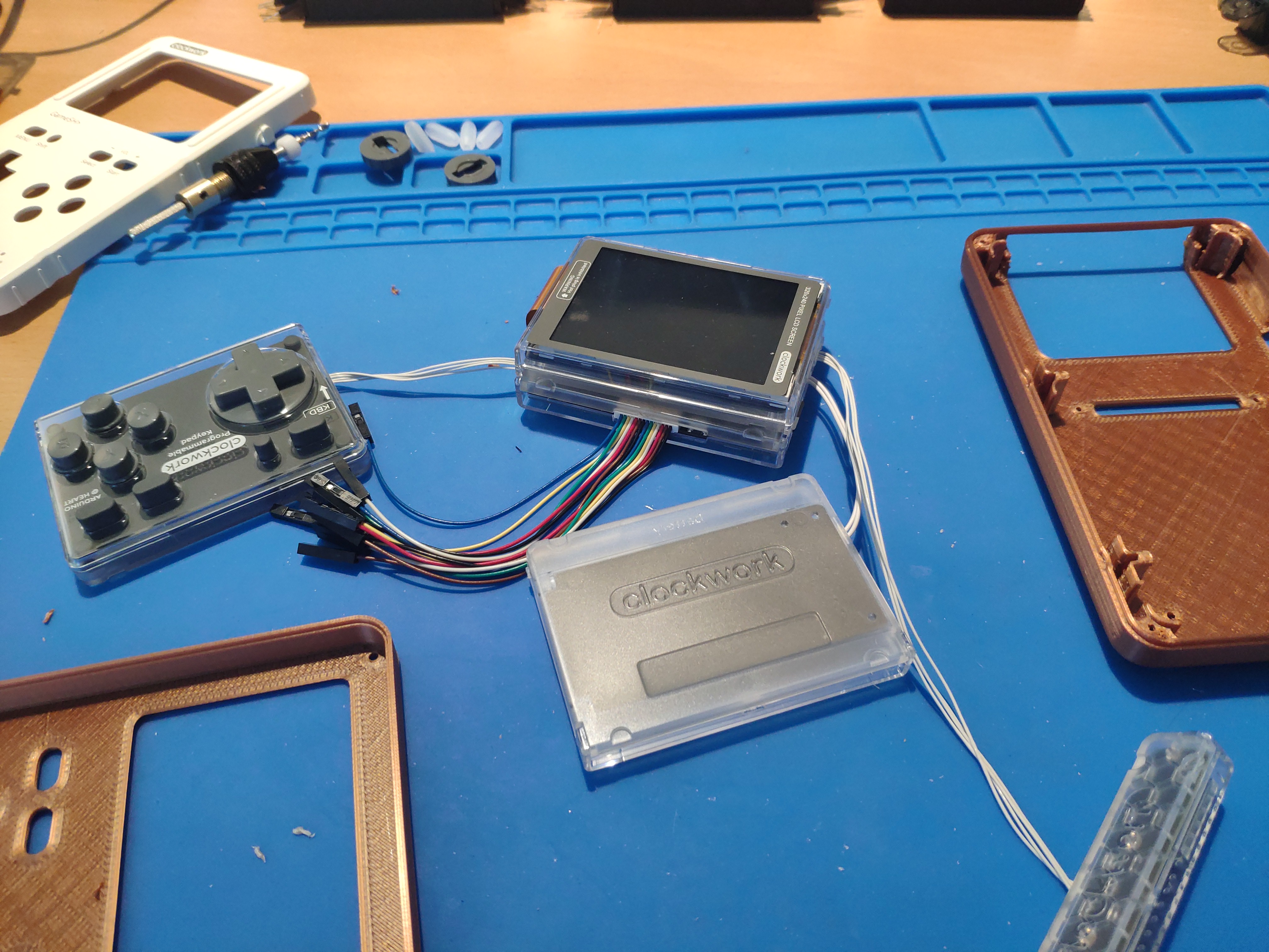
The Assembly
The assembly is very easy. The trickiest part will be to attach the thin display cable.
Assembly Tips
- remove the mainboard from its case when attaching the display cable
- attach the plastic buttons just before closing the case (otherwise they might fall off inbetween steps)
- a small pair of pliers will help removing the plastic elements from the packaging
- a small file is handy to clean up the plastic parts (otherwise the buttons wont run 100% smoothly)
- keep the display clean, and make sure it’s clean before proceeding. (I noticed a grain of dust on the display at the end :D )
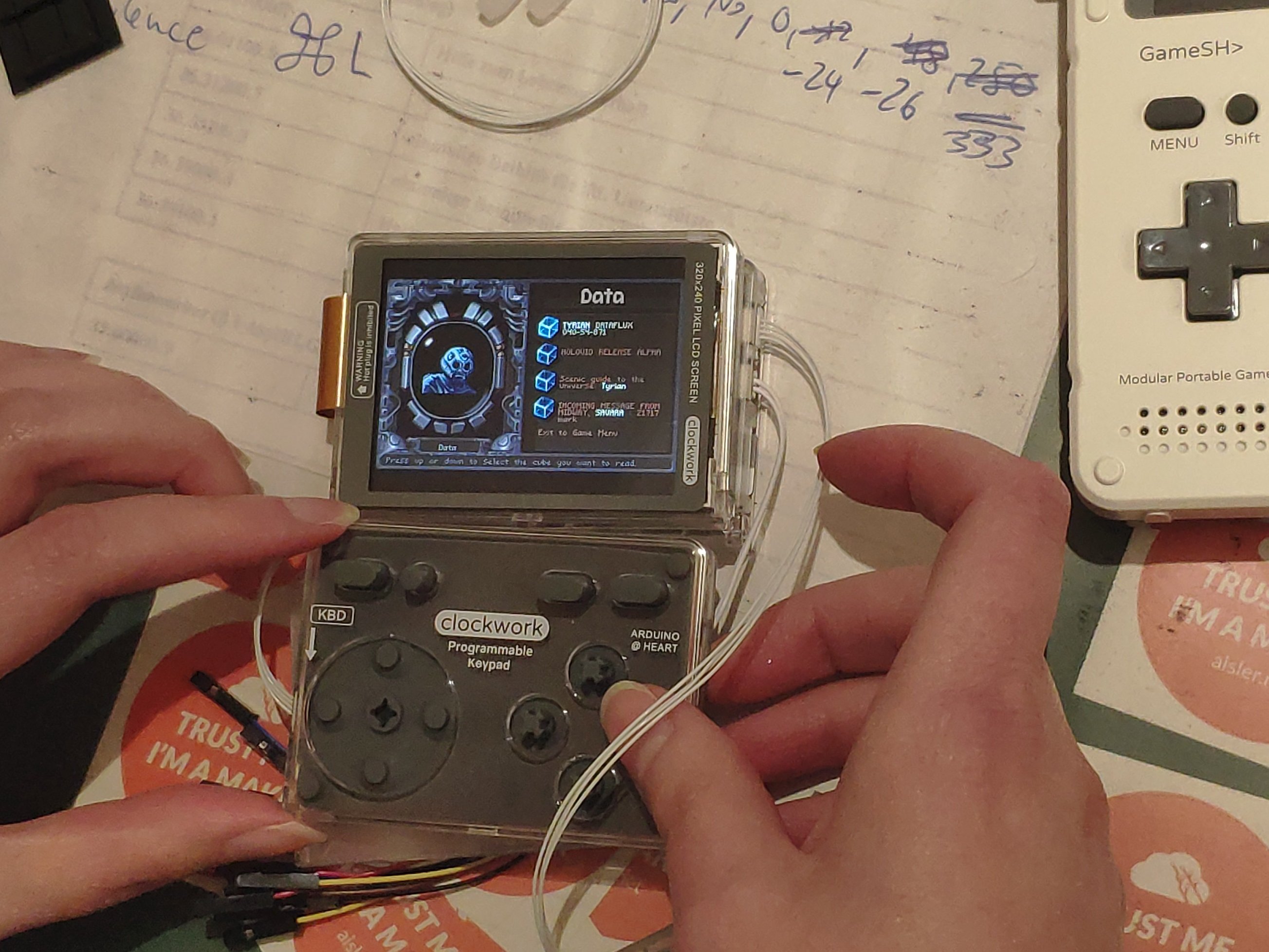
- test the connected modules work, before putting everything into the case

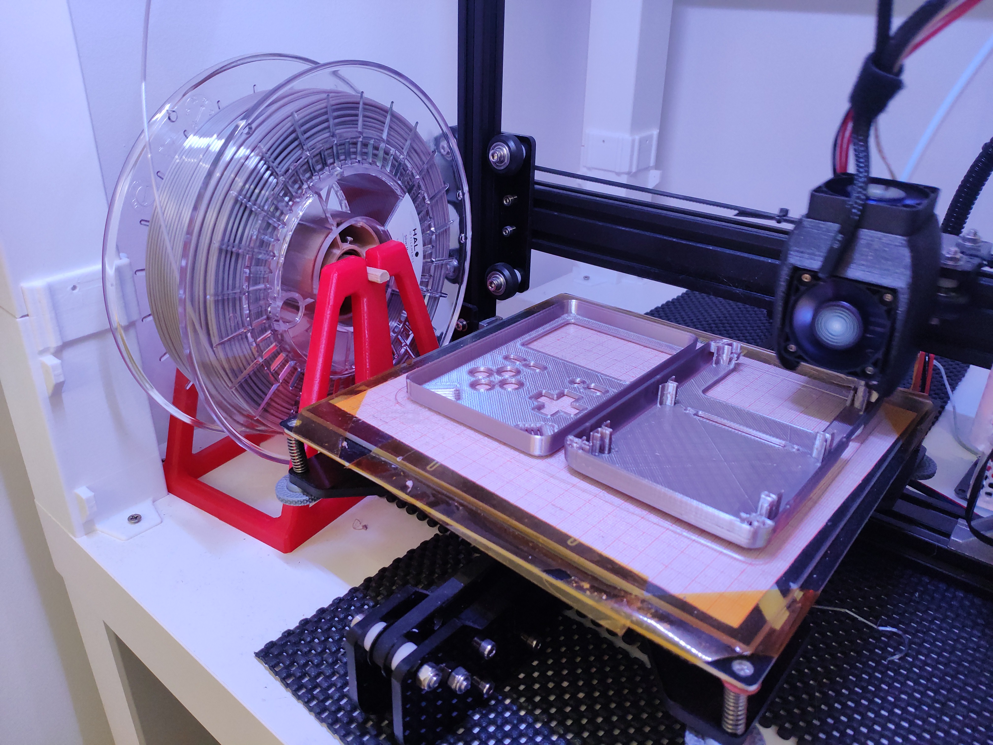
The 3D Print
The GPIO-cover


Game Development
I started to write down my findings in a new post: GameShell Game Development