GameShell GPIOs + Kernel Building
Table of Contents
- Intro
- Getting the GPIOs to work
- Using GPIOS directly via CLI
- Using I2C (/dev/i2c-0)
- SPI
- Building a new Kernel
Intro
The ClockworkPi GameShell comes with a GPIO expansion header. It provides access to 14 pins, that you can access with dupont cables.
Note: I wrote this post while I was figuring things out, so please be patient if it is not written linearly or not detailed enough.
Hopefully this provides you enough information to understand the GPIOs, and how to use them.
Getting the GPIOs to work
To get the GPIOs to work, we need to consider the avaiable information, i.e. find out which pin is which. This means we need to know how it is labeled on the outside of the GameShell, and to which pin this resolves on the CPU/SoC.
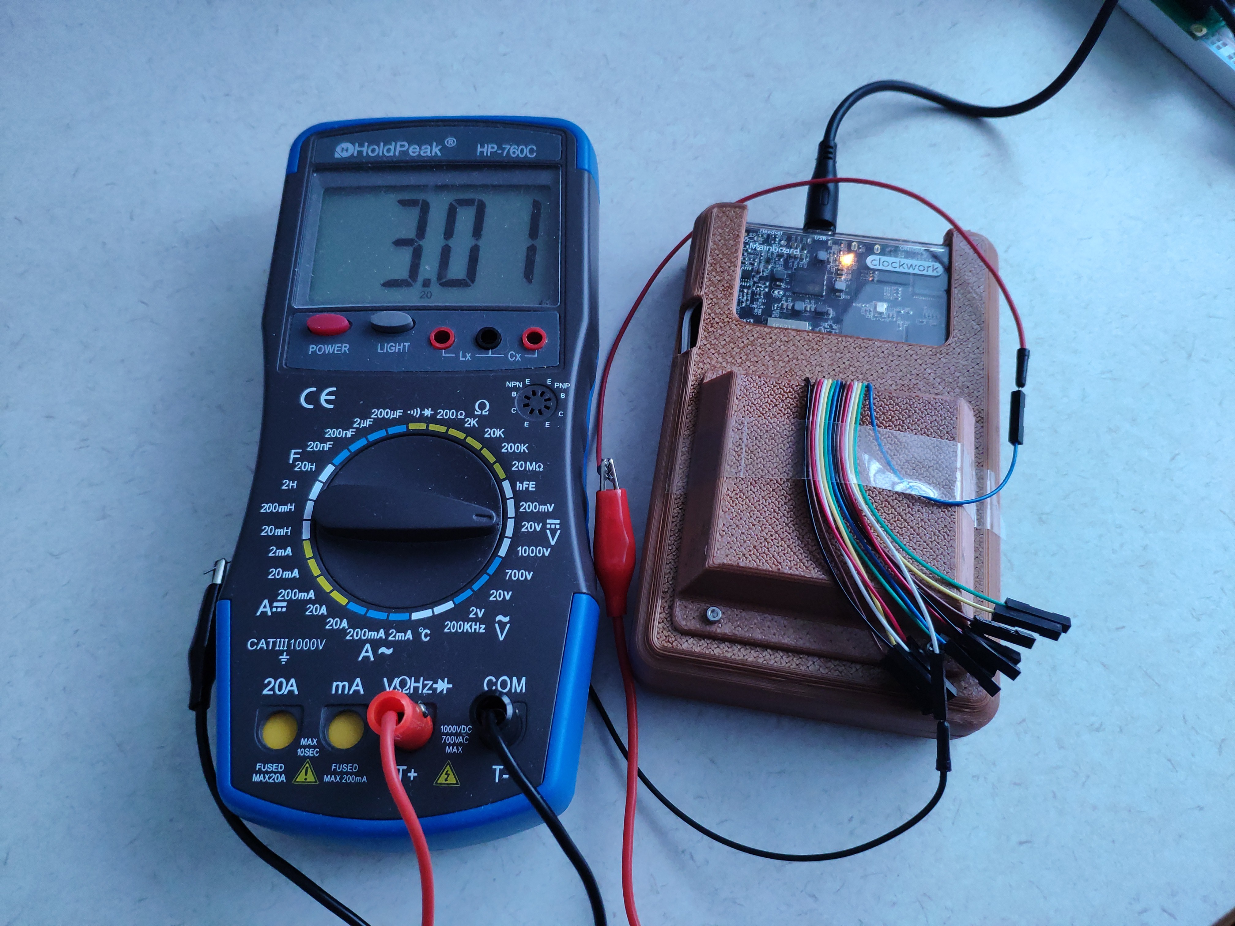
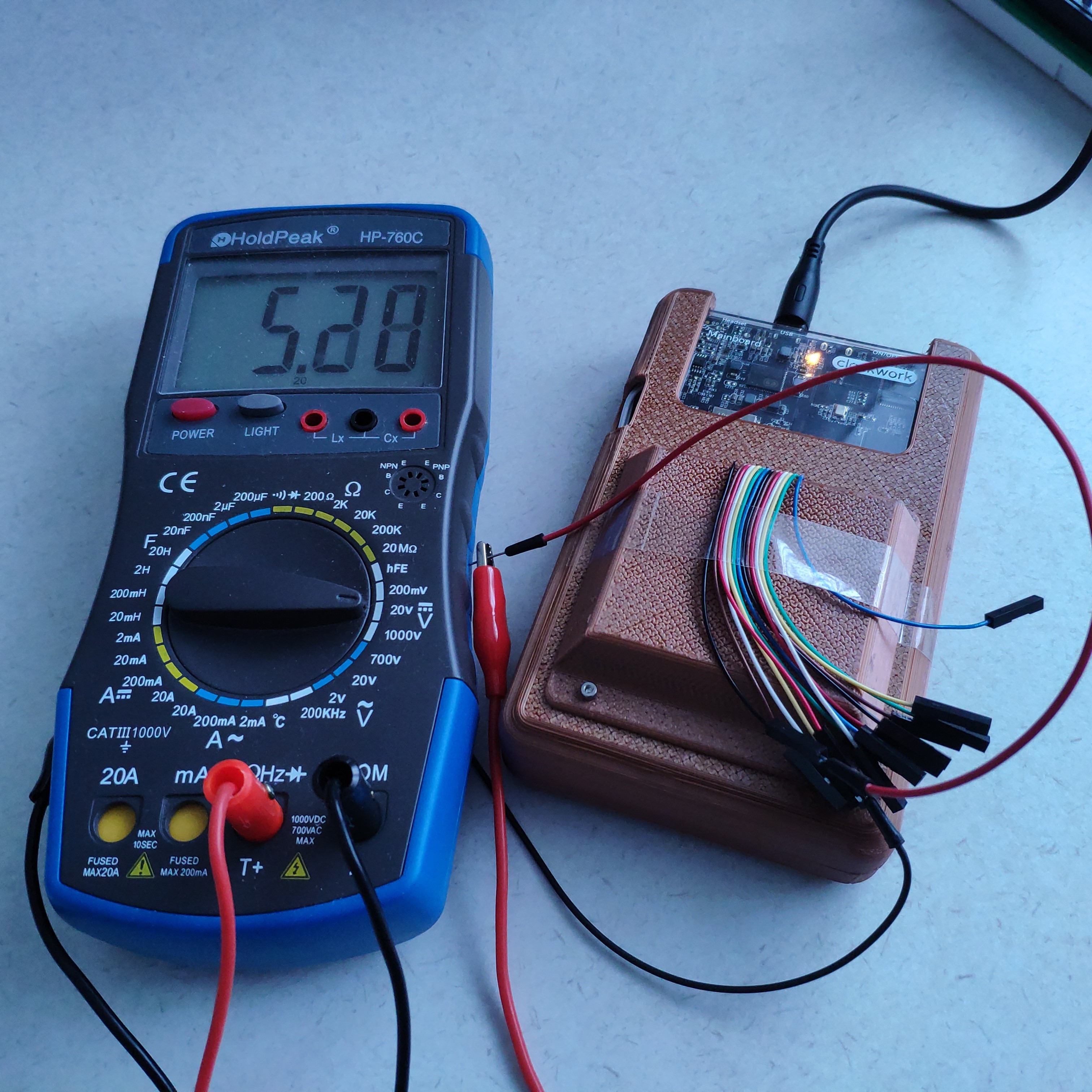
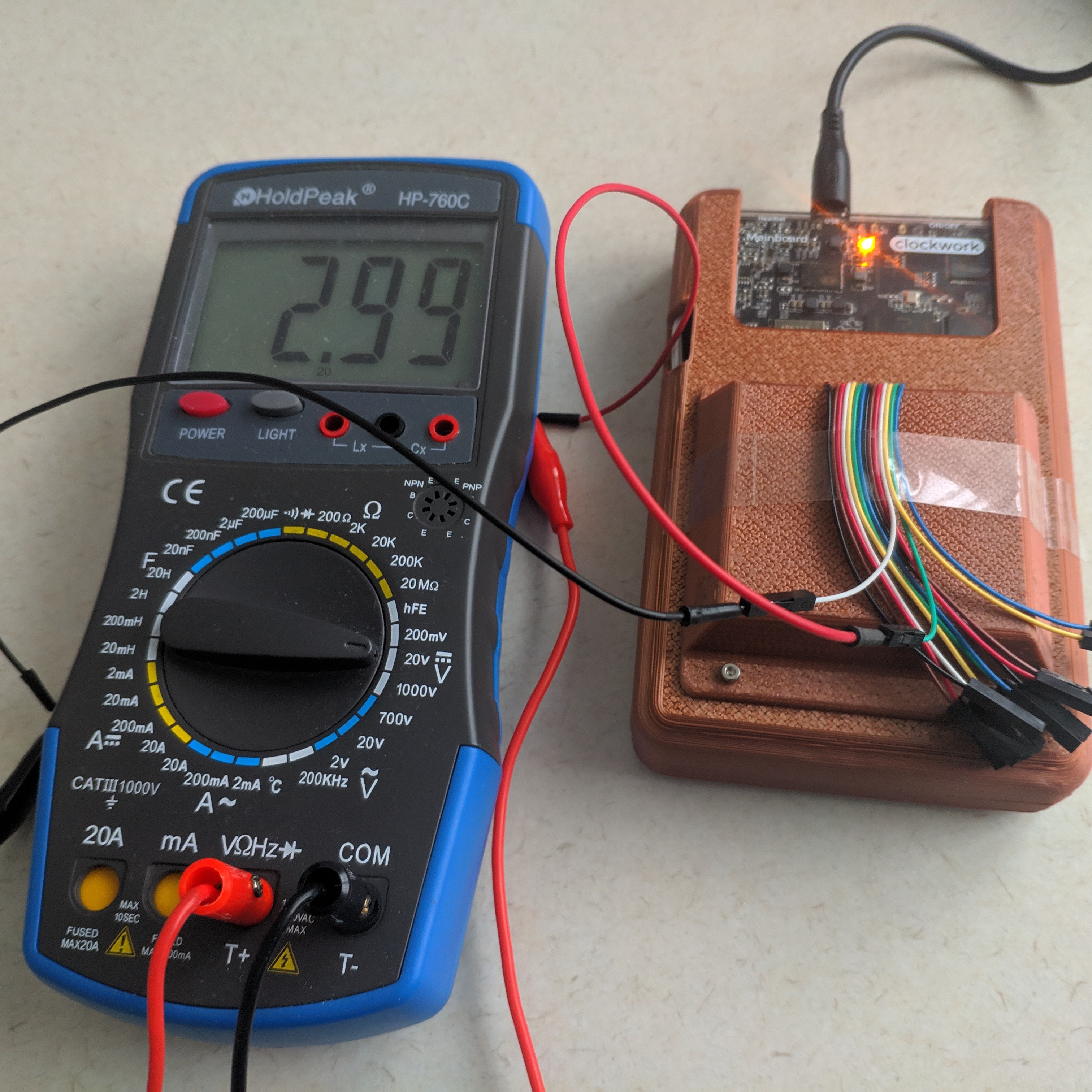
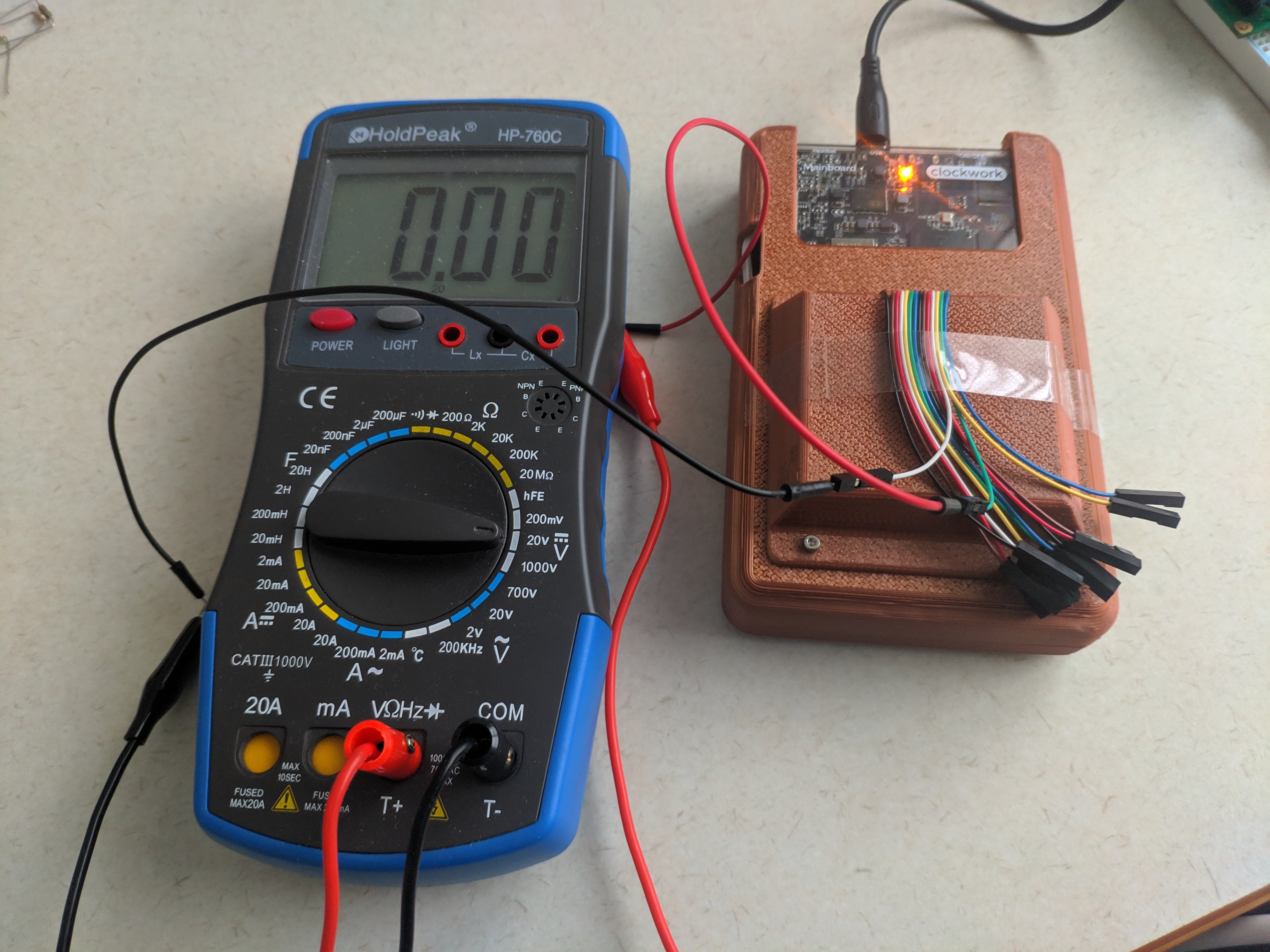
With the first information, we can check with a multimeter which pin is Pin 1, and verfiy the schematics, to get an orientation.
Then, we can check if we can change the output state of the pin (using the info from the SoC’s Datasheet) and verify with a multimeter if our assumptions are correct.
Only then we can proceed to try the next steps, for example I2C. I like to aproach these things with the smallest possible steps to find mistakes (on my side) as soon as possible. If you start with an unverified assumption, it will be harder to find, for example if it is a wiring error.
Research
There is a discussion thread in the clockworkpi forum, which already provides a lot of information. Part of the inormation you find in this post will match this thread. My usual aproach is to follow this from the bottom up to make sure I full understand how things work, and avoid breaking things ;).
The mainboard schematics in their GitHub repository:
https://github.com/clockworkpi/GameShellDocs/blob/master/clockwork_Mainboard_Schematic.pdf
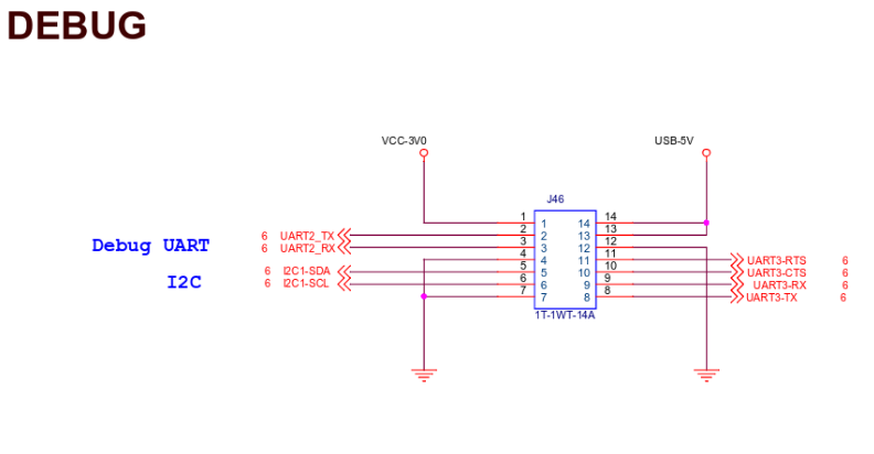


The GPIO expansion cable is connected at the bottom of this module.
This SoC is an Allwinner Technology R16-J, with the following datasheet:
https://linux-sunxi.org/images/b/b3/R16Datasheet_V1.4(1).pdf
Expansion Pins
We can combine the information of the schematics and the datasheet to get to the following table (I also added information from the sections below):
| Type | Pin # (ext.) | Pin # (Package) | Function 1 | Function 2 | Pin # (sysfs) | Color |
|---|---|---|---|---|---|---|
| 3V0 | 1 | blue | ||||
| GPIO | 2 | PB0 | UART0/2_TX | PB-EINT0 | 32 | green |
| GPIO | 3 | PB1 | UART0/2_RX | PB-EINT1 | 33 | yellow |
| GND | 4 | white | ||||
| GPIO | 5 | PH5 | I2C1-SDA | 229 | red | |
| GPIO | 6 | PH4 | I2C1-SCL | 228 | brown | |
| GND | 7 | black | ||||
| GPIO | 8 | PH6 | UART3-TX | SPI0-CS | 230 | blue |
| GPIO | 9 | PH7 | UART3-RX | SPI0-CLK | 231 | green |
| GPIO | 10 | PH9 | UART3-CTS | SPI0-MISO | 233 | yellow |
| GPIO | 11 | PH8 | UART3-RTS | SPI0-MOSI | 232 | white |
| GND | 12 | red | ||||
| 5V0 | 13 | brown | ||||
| 5V0 | 14 | black |
We see, we have Serial pins, I2C pins and SPI pins. According to the datasheet we can also use these ports as GPIOs.
Pin Order
Important: The colors have nothing to do with +,-, or GND, and so on. Please make sure _NOT_ to make any assumptions by the colors. Always check your cables have the same color ordering.Then, refer to the table above for pin details.
Using GPIOS directly via CLI
First, become root:
sudo su
Next, I want to access the GPIO pins using the sysfs interface.
cd /sys/class/gpio
ls
Which returns
export gpiochip0 gpiochip352 unexport
To access the pins as GPIO we can now map them into this interface. You can find more details on this on this page:
From this page, you will find that the a package pin, for example PB0 or PB1 are assigned a sysfs number for this interface.
The rule to calculate this number is
(position of letter in alphabet - 1) * 32 + pin number
So for PB0 this results in (2 - 1) * 32 + 0 = 32 and for PB1 it’s (2 - 1) * 32 + 1 = 33.
I updated the table above acordingly.
Note: I am running Kernel 5.2.0-rc4-clockworkpi-cpi3 (compiled, as described below)
Then, create the pin’s interface:
echo 32 > /sys/class/gpio/export
which creates the interface’s pin directory:
cd /sys/class/gpio/gpio32/ # PB0, green cable
Which contains the following files
active_low device direction edge power subsystem uevent value
To use this pin as an output pint you can configure it
echo out > direction
And enable it
echo 1 > value
or disable it
echo 0 > value
I will leave it to the reader to test this for the echo in > direction, echo value case ;).
Using I2C (/dev/i2c-0)
There is a command line tool i2cdetect that can scan for devices connecte to the I2C port.
Out of the box this complains
root@clockworkpi:/home/cpi# i2cdetect 1
Error: Could not open file `/dev/i2c-1' or `/dev/i2c/1': No such file or directory
because there is not a single I2C entry listed under /dev/i2c-X out of the box.
Enabling I2C via Device Tree
(See the section below how to get the Kernel Sources)
Go to linux-5.2-rc4/arch/arm/boot/dts.
Here, I added the following section to sun8i-r16-clockworkpi-cpi3.dts
&i2c1 {
    status = "okay";
}
and build with (like the kernel build section below, if you have previously built the kernel, this will be quick)
make ARCH=arm CROSS_COMPILE=arm-linux-gnueabihf-
Copy over the new file to your GameShell
scp arch/arm/boot/dts/sun8i-r16-clockworkpi-cpi3.dtb cpi@clockworkpi:/home/cpi/
Connect to your game shell and mount the boot partition:
ssh cpi@clockworkpi
sudo su
cd /mnt
mkdir boot
mount /dev/mmcblk0p1 /mnt/boot/
Make a backup to be safe(!):
cp /mnt/boot/sun8i-r16-clockworkpi-cpi3.dtb /mnt/boot/sun8i-r16-clockworkpi-cpi3.dtb.bak
Install the new device tree file:
mv /home/cpi/sun8i-r16-clockworkpi-cpi3.dtb /mnt/boot/sun8i-r16-clockworkpi-cpi3.dtb
I2C Scan
You can scan the I2C bus with (as root):
root@clockworkpi:/home/cpi# i2cdetect 0
If you have nothing attached to the I2C Pins you will get:
WARNING! This program can confuse your I2C bus, cause data loss and worse!
I will probe file /dev/i2c-0.
I will probe address range 0x03-0x77.
Continue? [Y/n]
    0  1  2  3  4  5  6  7  8  9  a  b  c  d  e  f
00:          -- -- -- -- -- -- -- -- -- -- -- -- --
10: -- -- -- -- -- -- -- -- -- -- -- -- -- -- -- --
20: -- -- -- -- -- -- -- -- -- -- -- -- -- -- -- --
30: -- -- -- -- -- -- -- -- -- -- -- -- -- -- -- --
40: -- -- -- -- -- -- -- -- -- -- -- -- -- -- -- --
50: -- -- -- -- -- -- -- -- -- -- -- -- -- -- -- --
60: -- -- -- -- -- -- -- -- -- -- -- -- -- -- -- --
70: -- -- -- -- -- -- -- --
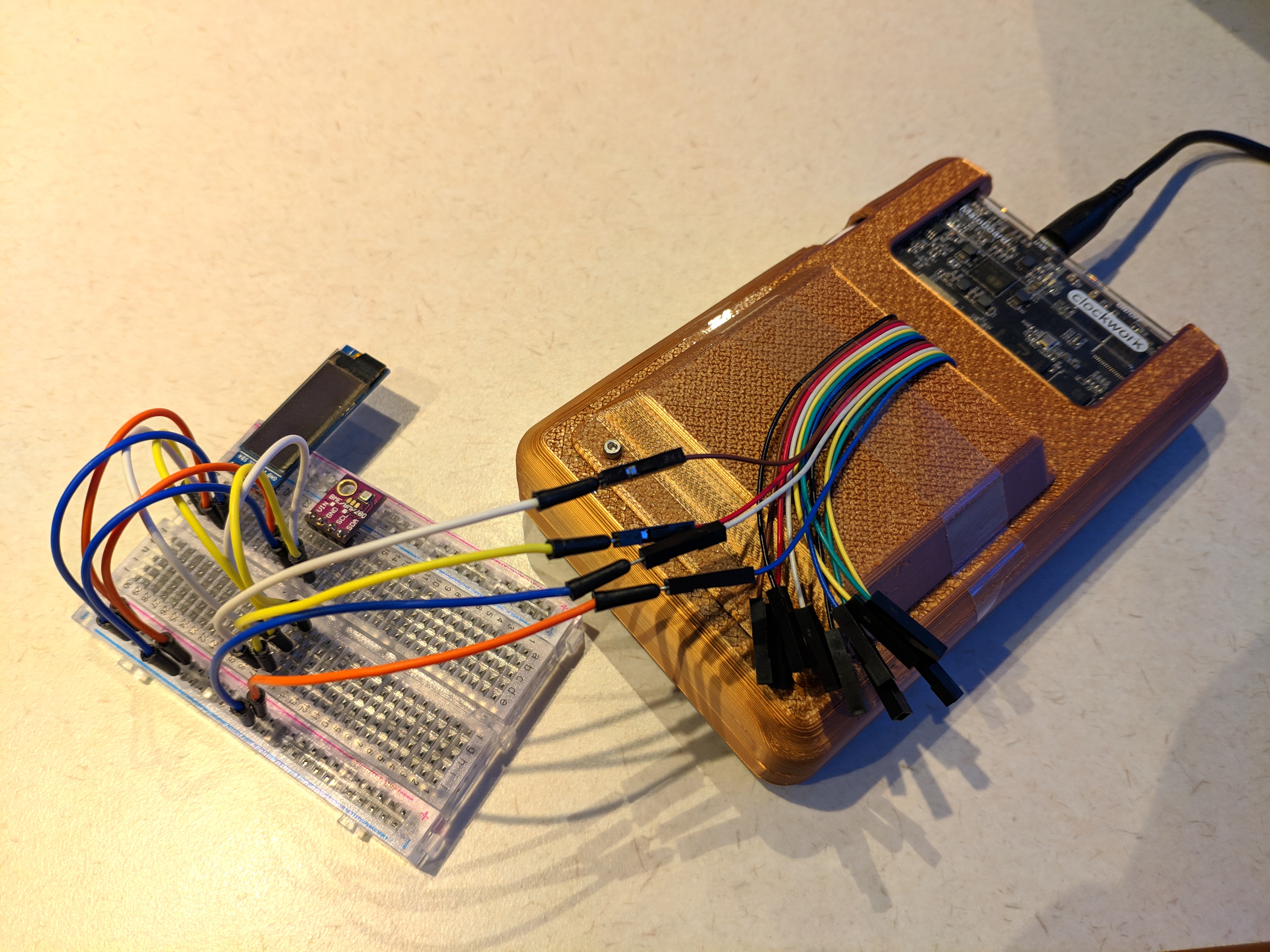
- VIN -> blue (1)
- GND -> white (4)
- SDA -> red (5)
- SCL -> brown (6)
If you connect a Bosch BME280 sensor and a Oled 32x128 SSD1306 display you get:
WARNING! This program can confuse your I2C bus, cause data loss and worse!
I will probe file /dev/i2c-0.
I will probe address range 0x03-0x77.
Continue? [Y/n]
    0  1  2  3  4  5  6  7  8  9  a  b  c  d  e  f
00:          -- -- -- -- -- -- -- -- -- -- -- -- --
10: -- -- -- -- -- -- -- -- -- -- -- -- -- -- -- --
20: -- -- -- -- -- -- -- -- -- -- -- -- -- -- -- --
30: -- -- -- -- -- -- -- -- -- -- -- -- 3c -- -- --
40: -- -- -- -- -- -- -- -- -- -- -- -- -- -- -- --
50: -- -- -- -- -- -- -- -- -- -- -- -- -- -- -- --
60: -- -- -- -- -- -- -- -- -- -- -- -- -- -- -- --
70: -- -- -- -- -- -- 76 --
\o/.
SPI
// TODO: sorry :)
Building a new Kernel
Sources
This repo provides what you need to build the kernel:
https://github.com/clockworkpi/Kernel
The following assumes you are building for
Prepare the sources (we are going to work in a directory called cpi-0.4-kernel-5.2)
mkdir cpi-0.4-kernel-5.2
cd cpi-0.4-kernel-5.2/
wget https://git.kernel.org/torvalds/t/linux-5.2-rc4.tar.gz
tar xf linux-5.2-rc4.tar.gz
cd linux-5.2-rc4
wget https://raw.githubusercontent.com/clockworkpi/Kernel/master/v0.4/52rc4.patch
git apply 52rc4.patch
Toolchain
Prepare your tool chain (back in cpi-0.4-kernel-5.2)
cd cpi-0.4-kernel-5.2/
https://releases.linaro.org/components/toolchain/binaries/7.2-2017.11/arm-linux-gnueabihf/gcc-linaro-7.2.1-2017.11-x86_64_arm-linux-gnueabihf.tar.xz
tar xf gcc-linaro-7.2.1-2017.11-x86_64_arm-linux-gnueabihf.tar.xz
I had to install some missing packages (on Debian 10.2):
apt-get install flex bison libssl-dev u-boot-tools
This might be an incomplete list of missing packages, and if you have a different setup, it will likely fail in the make step below. In this case you have to google your error message and check what package is missing on your system.
add the compiler to the path:
cd gcc-linaro-7.2.1-2017.11-x86_64_arm-linux-gnueabihf/bin/
export PATH=$PATH:$(pwd)
Compiling
Go to the source (using the session with the updated $PATH variable above)
cd ../../linux-5.2-rc4
cp ./arch/arm/configs/clockworkpi_cpi3_defconfig .config
make ARCH=arm CROSS_COMPILE=arm-linux-gnueabihf-
mkimage -A arm -O linux -T kernel -C none -a 0x40008000 -e 0x40008000 -n "Linux Kernel" -d arch/arm/boot/zImage uImage
Now, you should have the file uImage, your freshly built kernel.
Installing a new Kernel
First we copy over the uImage from our build machine:
scp uImage cpi@clockworkpi:/home/cpi/
On the GameShell, you need to mount the /boot partition:
ssh cpi@clockworkpi
sudo su
cd /mnt
mkdir boot
mount /dev/mmcblk0p1 /mnt/boot/
It makes sense to create a backup first.
cd /mnt/boot/
cp uImage uImage.bak
..and replace the uImage file.
cp /home/cpi/uImage ./uImage
reboot